Harmonic Mitigation & Bearing Current Protection in Variable-Speed HVAC EC Motors: An OEM Integration Guide
An engineering analysis of inverter-induced common-mode voltages (CMV), capacitive parasitic bearing fluting, and grid harmonic distortion (THDi) in commercial HVAC EC motors. Learn how active PFC and hybrid ceramic shaft protection extend L10h bearing life past 50,000 hours.
Variable-Speed EC Motors in High-Duty Commercial HVAC
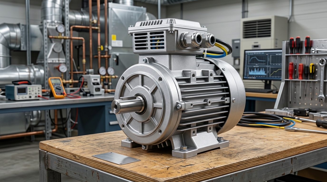
Electronically Commutated (EC) and permanent magnet brushless DC (BLDC) motors have become the efficiency benchmark for commercial air handling units (AHUs), rooftop packaged equipment, fan coil units, and cooling towers. Driven by integrated pulse-width modulation (PWM) inverters, these systems routinely exceed IE5 Ultra-Premium efficiency standards. However, the high switching speeds of modern IGBT and silicon carbide (SiC) power semiconductors—with voltage rise rates (\(dv/dt\)) frequently exceeding \(5 ext{ to } 8 ext{ kV}/\mu ext{s}\)—introduce acute parasitic phenomena: inverter-induced common-mode voltages (CMV) and high-frequency bearing EDM currents, coupled with grid-side Total Harmonic Distortion (THDi).
Left unaddressed, capacitive shaft voltages discharge through thin hydrodynamic lubricant films inside motor ball bearings, causing Electrical Discharge Machining (EDM), microscopic melting craters, washboard fluting tracks, and premature mechanical breakdown. This technical guide outlines the physics of bearing degradation and details MYSUN Power's integrated dual-defense architecture for commercial HVAC OEMs.
1. Root Cause Analysis: Inverter Common-Mode Voltage & Bearing Fluting
In a balanced three-phase sinusoidal power supply, the neutral sum of phase-to-ground voltages is mathematically zero: \(V_u + V_v + V_w = 0\). Conversely, in a variable-frequency inverter utilizing two-level space vector PWM, the instantaneous three-phase sum is never zero. Instead, a neutral common-mode step voltage (\(V_{cm}\)) alternates between \(+ rac{1}{6}V_{dc}\) and \(+ rac{1}{2}V_{dc}\) at the PWM carrier switching frequency (typically 8–16 kHz).
Parasitic Capacitive Voltage Divider Ratio (BVR):
The motor behaves as an electrostatic network where stray parasitic capacitances govern shaft potential: $$\text{BVR} = \frac{V_{\text{shaft}}}{V_{cm}} = \frac{C_{wr}}{C_{wr} + C_{rf} + 2C_b}$$ Where \(C_{wr}\) is winding-to-rotor capacitance, \(C_{rf}\) is rotor-to-frame capacitance, and \(C_b\) is bearing film capacitance. In unshielded commercial motors, BVR typically ranges from 5% to 15%, generating peak shaft voltages (\(V_{\text{shaft}}\)) of 15V to 45V.
When the shaft voltage exceeds the dielectric breakdown threshold of the synthetic bearing grease (normally 8V to 15V depending on temperature, viscosity, and film thickness), an arc discharge flashes across the rolling elements. The localized thermal flash vaporizes microscopic steel particles, causing acoustic whine, grease blackening (carbonization), and distinctive washboard "fluting" across the outer raceway.
2. Power Quality: Mitigating Harmonic Currents (THDi) to Meet IEEE 519
Commercial HVAC installations in hospitals, university campuses, and Tier III/IV data centers impose strict limits on grid harmonic pollution. Unfiltered three-phase bridge rectifiers typically induce non-linear current harmonics with \(THDi > 35\%\), which overheat facility distribution transformers, trip sensitive circuit breakers, and degrade power factors down to 0.70–0.78.
To achieve seamless building integration, MYSUN integrates Active Power Factor Correction (Active PFC) and optimized DC bus choke filtering into commercial EC drive topologies:
- Continuous Current Shaping: Real-time boost-stage PFC shapes incoming AC line current into a pure sinusoid in phase with line voltage, reducing \(THDi\) below 5% across 20%–100% operating loads.
- Displacement Power Factor \(\cos \phi > 0.98\): Eliminates penalty billing from commercial electrical utilities without requiring bulky external capacitor banks.
- Wide Input Voltage Immunity: Wide-range PFC stages maintain constant DC link bus voltage under grid sags (180V–264V single-phase / 320V–480V three-phase), preventing fan speed drop during peak summer cooling hours.
3. MYSUN Dual-Defense Architecture: Mechanical & Electrical Protection
Guangdong MYSUN Power Technology Co., Ltd. incorporates a multi-tiered mitigation matrix specifically engineered for commercial continuous-run HVAC equipment:
Tier 1: Conductive Shaft Grounding Rings (SGR)
High-density micro-conductive carbon filaments (millions of fibers positioned around the 360° shaft perimeter) provide an ultra-low impedance galvanic shunt path directly from the rotor shaft to the motor end-bell. Shaft voltage is securely clamped below 1.5V, rendering destructive EDM arc discharges physically impossible.
Tier 2: Ceramic Hybrid Ball Bearings (Si₃N₄)
For critical cleanroom AHUs and high-capacity centrifugal chillers, MYSUN equips the non-drive end with silicon nitride (\(\text{Si}_3\text{N}_4\)) ceramic rolling elements. Providing electrical insulation breakdown resistance exceeding 2.5 kV, this configuration breaks high-frequency magnetic circulating loop currents entirely.
4. Engineering Performance Comparison
| Performance Metric | Standard AC Induction + VFD | Generic Commercial EC Motor | MYSUN Protected HVAC EC Motor |
|---|---|---|---|
| Total Harmonic Distortion (THDi) | 35% ~ 48% (Unfiltered) | 18% ~ 28% | < 4.8% (IEEE 519 Compliant) |
| Peak Shaft Voltage (\(V_{\text{pk}}\)) | 22V ~ 40V (High EDM risk) | 14V ~ 25V | < 1.8V (Zero Discharge) |
| Bearing L10h Service Life | 12,000 ~ 18,000 hours | 20,000 ~ 25,000 hours | > 50,000 hours continuous |
| Acoustic PWM Tonal Whine | Prominent 4–8 kHz pitch | Moderate 12 kHz tone | Suppressed (Spread-Spectrum FOC) |
| Efficiency Compliance | IE2 / IE3 | IE4 Super Premium | Exceeds IE5 Ultra-Premium |
5. OEM Installation & Grounding Best Practices
Even the most advanced motor protection system relies on sound mechanical and electrical installation practices. For commercial HVAC equipment manufacturers, MYSUN engineers recommend adhering to the following installation protocol:
- Low-Impedance Frame Bonding: Ensure high-frequency bonding between the motor stator casing, fan scroll housing, and AHU framework with flat braided copper straps (bonding resistance < 0.1 \(\Omega\)). Avoid relying on painted bolt threads.
- Shielded Symmetrical Cabling: When using external drive enclosures, utilize symmetrical 3-phase + 3-ground cables with continuous 100% copper braid or aluminum tape shielding terminated 360° at both the motor terminal box and drive cabinet gland.
- EMC Filter Placement: Position integrated line filters within 300mm of the mains entry point to prevent high-frequency noise from coupling into adjacent Modbus RS-485 or BACnet communication trunks.
Consult MYSUN HVAC Engineering
Whether retrofitting existing direct-expansion fan arrays or designing next-generation rooftop commercial air conditioners, our Guangdong technical team provides custom EC motor prototypes engineered to your exact voltage, airflow, static pressure, and acoustic specifications.
Ready to Optimize Your Motor Performance & Lower TCO?
Guangdong MYSUN Power Technology Co., Ltd. delivers customized BLDC, EC, and high-torque geared motor solutions tailored to your thermal, mechanical, and efficiency specs. Engineering proposals in 14–30 days; prototype batches (3–5 units) and production timelines confirmed following engineering review.